Add bearing walls - Exercise
During these tasks, we shall continue the development of the structural model by adding the sub-structure that makes up the building's foundations.
Task 1: Adding bearing walls
During this task we are going to step through a workflow for adding below-ground bearing walls.
- Open the project STRUCTURAL (Creating Sub-structure Bearing Walls Start).rvt.
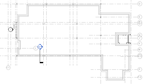
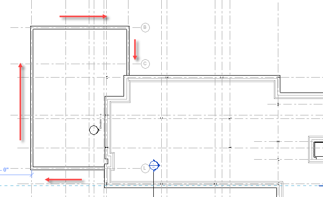
- Open the Ground Floor view in which the ARCHITECTURAL and MEP links have been switched off and we are using the floor slab and grid lines to indicate where the bearing walls should be added.
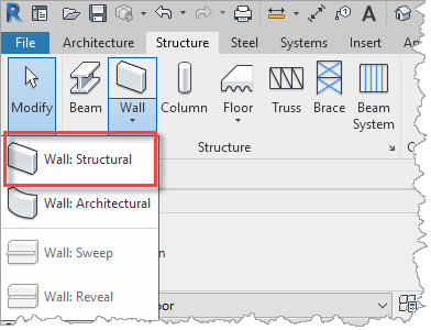
- From the Structure ribbon, select Wall, then select Wall: Structural.
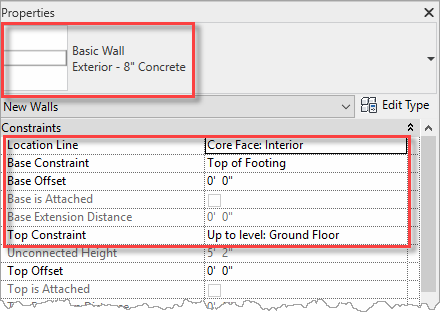
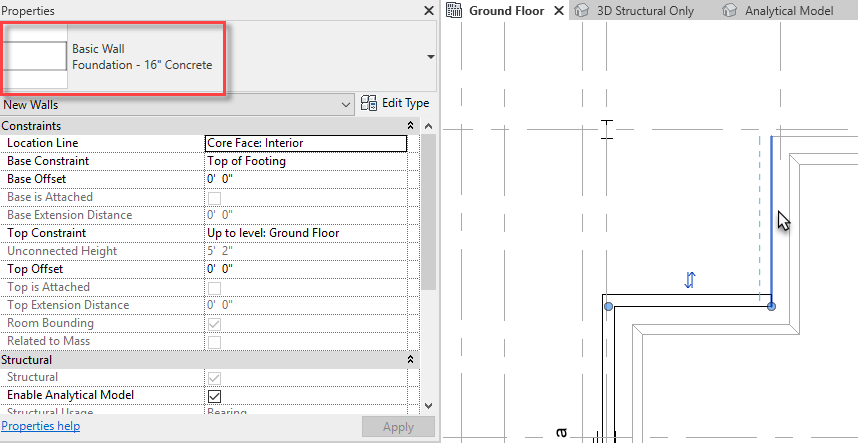
- Set the Wall Type to Foundation – 8" Concrete. For the Location Line, we shall be butting the wall up against the slab, so shall use Core Face: Interior. For the Base Constraint, we shall select the Top of Footing. The Top Constraint has defaulted to the current level which is the Ground Floor.
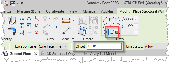
- Select the Pick Lines Draw option from the ribbon an ensure that the Offset is set to 0'-0". This will enable us to place the foundation along the edges of the slab.
- Add the bearing wall around the perimeter of the ground floor slab by picking on the slab edges, starting from the lower left corner of the slab, for example.
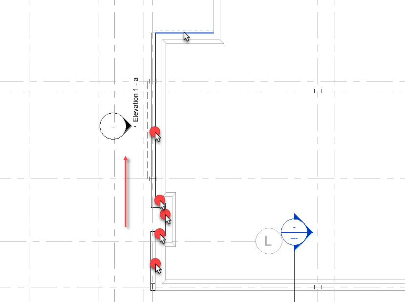
- At grid line 6, change the bearing wall to Foundation – 16" Concrete.
- Continue right around the perimeter of the slab, back to the start corner.
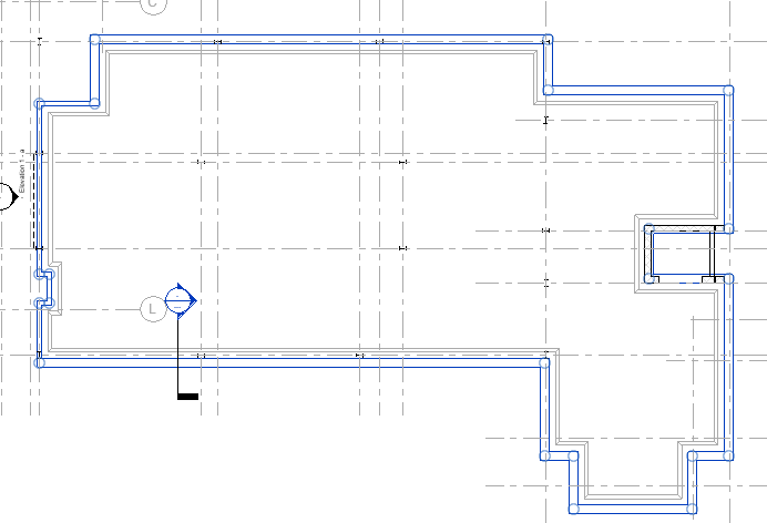
- We shall now add an extra bearing wall to the lower-level part of the building. These walls will be centered on the grid lines, so we shall change the Draw option to Line and ensure the Chain option is enabled.
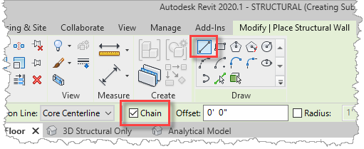
- In the Properties palette, set the Location Line to Core Centerline, set the Top Constraint to Lower Level, and trace along these gridlines.
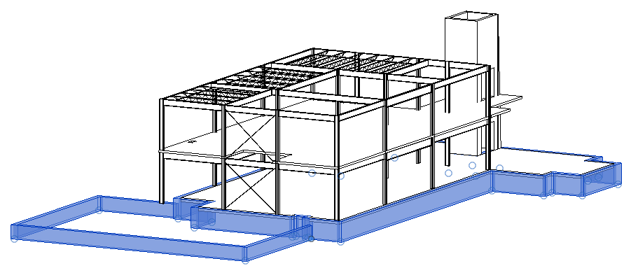
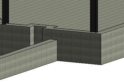
- Switching to the 3D Structural Only view, we can see the bearing wall running around the underside of the structural model.
- Save the project so that it can be used in the next objective which will be to assign consistent concrete materials to the foundation.
Task 2: Assigning materials
Next, we shall review the materials assigned the various concrete building objects. Whilst the material assignment is only indicative and can be changed by the structural analysis program, it is good practice to assign materials consistently is it impacts how Revit draws details and assigns outlines to separate components.
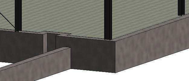
- One good way of spotting inconsistent materials is to display the model using the Realistic visual style in a 3D view, for example, we can clearly see that the floor slab and bearing walls have a different material pattern.
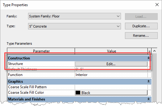
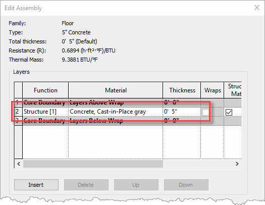
- First, let's look at the material assigned to the ground floor slab. To do this, select the slab and then use Edit Type in the Properties palette to open the Type Properties dialog. Within this dialog, select the Edit button next to the Construction Structure.
- In the Edit Assembly dialog, we can see that the slab is constructed from a single component that has been assigned Concrete, Cast-in-place gray material. We shall not change this, so will cancel out the dialogs ready to assign the same material to the other concrete objects.
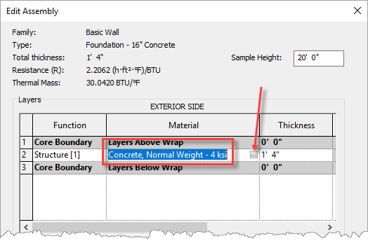
- As with the ground floor slab, repeat the procedure to review the material assigned to the Foundation - 16" Concrete bearing wall Type Properties. Through the Edit Assembly dialog, we can see that it has been assigned the material of Concrete, Normal Weight – 4 ksi. To change this material, select the button with three dots to the right of the material name.
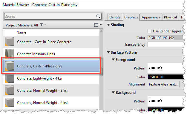
- This will open the Material Browser. Change the material to Concrete, Cast-in- place gray to be consistent with the slab.
- To confirm the material change, OK the Material Browser dialog, then OK the Edit Assembly dialog, and finally OK the Type Properties dialog. The slab and bearing walls now have the same material in the shaded view.
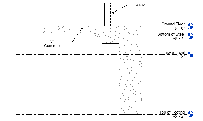
- Switch to the Section 1 - Callout 1 callout view that has a detail of a cross section through the slab and the foundation. Notice that the slab edge does not include the concrete fill pattern – this also indicates that it does not have concrete material assigned to it.
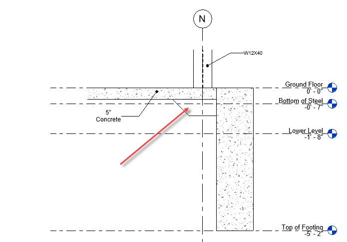
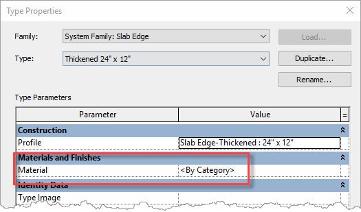
- In the Type Properties dialog for the slab edge, we can see that its Material is set to <By Category>. Whilst we could simply set the same concrete material here, we shall take this opportunity to explain how materials are assigned according to their category, so we shall cancel this dialog.
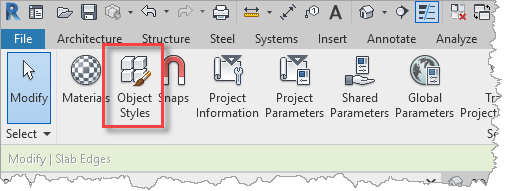
- From the Manage ribbon, select Object Styles.
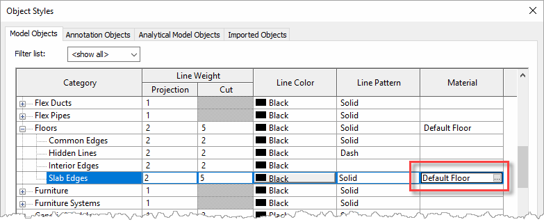
- The Object Styles dialog is the interface for assigning a material to an object category. In the case of the slab edge, scroll down and expand Floors and then select Slab Edges. Here we see that the slab edge category is currently assigned the material Default Floor. Change the material to Concrete, Cast-in-place gray by opening the Material Browser in the same way as before.
- Close the Object Styles with OK to commit the change and the detail is updated with the slab edge displaying the concrete fill pattern. Plus, since it uses the same material as the slab and it automatically merges with the slab, the detail indicates that this part of the same concrete pour and that they are not separate concrete objects.
- Save the project so that it can be used in the next objective which will be to continue the development of the foundations through the additional of pads and piers.


