Exercise 16–Dimensions and Tags
We have seen dimensions used as a tool for editing the model, but naturally we will want to use dimensions for documentation purposes as well. There are some features that help speed up the placement of dimensions for documenting your design.
Catch-up file completed to this point: 16_Medical Center_Annotation.rvt
Dimensioning Walls
The default behavior of the dimension tool requires you to place each witness line. When dimensioning walls, you have an option that can be much quicker. Let’s start with a new version of the first floor plan for this.
- On the Project Browser, right-click the Level 1 floor plan and choose: Duplicate View > Duplicate (see ).

Figure 16–1 Duplicate the Level 1 Plan
- Right-click the new view and choose: Rename. Name it: Level 1 Dimension Plan.
Notice that this is a clean copy of the floor plan with none of the previous tags or dimensions. Not to worry, the model is still live. Any change in this view will affect geometry and annotation in other views.
- Zoom in on the horizontal wall above the exam rooms at Grid D.
- On the Annotate tab, click the Aligned Dimension tool (or press di).
- On the Options Bar, for the “Pick” option, choose: Entire Walls (see Figure 16–2).
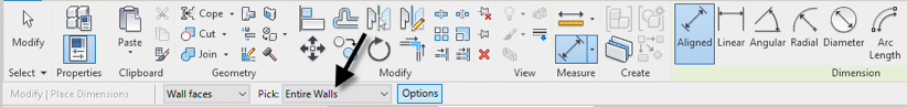
Figure 16–2 Use the Entire Walls option to speed dimensioning of walls
- Click the exterior wall at Grid D.
A dimension will appear along the length of the wall.
- Move above the wall, just below the grid bubbles and click to place the dimension (see Figure 16–3).
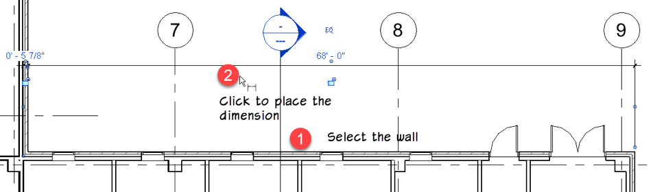
Figure 16–3 Place the first dimension
- Stay in the dimension command. On the Options Bar, click the Options button right next to the “Pick” drop-down.
- In the “Auto Dimension Options” dialog, check the Intersecting Grids checkbox and then click OK (see Figure 16–4).

Figure 16–4 Add grids to the automatic dimensioning
- Click the same wall again. Place the dimension below the first one (see Figure 16–5).
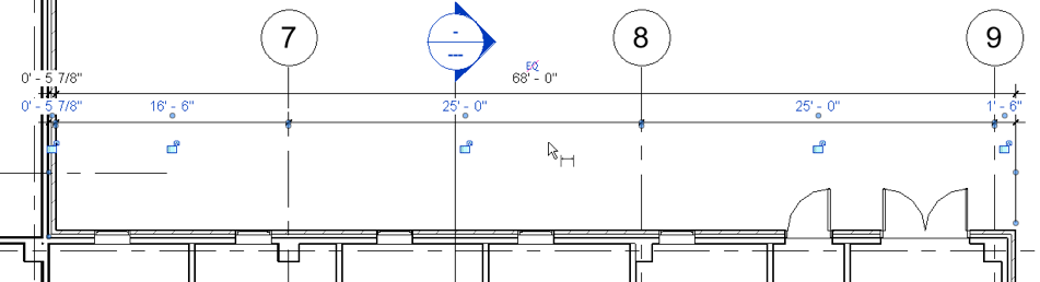
Figure 16–5 Add the next string including the grids
- Stay in the dimension command. On the Options Bar, click the Options button again.
- In the “Auto Dimension Options” dialog, check the Openings checkbox and choose the Width option. Uncheck the Intersecting Grids checkbox and then click OK (see Figure 16–4).

Figure 16–6 Add openings to the automatic dimensioning
- Click the same wall again. Place the dimension below the first one (see Figure 16–7).
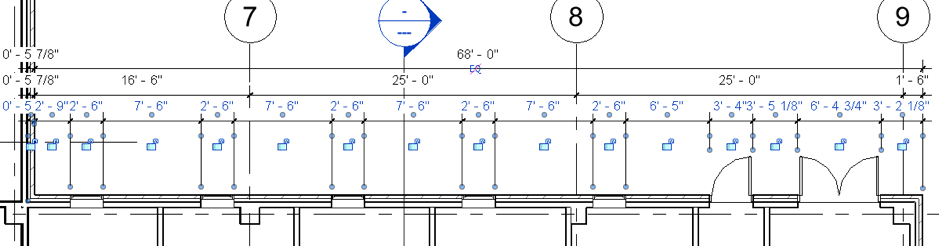
Figure 16–7 Add a final string including the openings
- Click the Modify tool or press esc twice to cancel.
Modifying Dimensions
The atomically generated dimensions are very quick, but sometimes you need to make slight adjustments.
On the right side, (near Grid 9) the text of two values are overlapping making it difficult to read.
- Select the lowest dimension string.
Note the small round controls beneath each piece of text.
- Drag the small text control for the right-most value to move the text away from the dimension string (see ).

Figure 16–8 Drag text as required to make dimensions more legible
- Repeat for any values that require it.
On the left side of the dimensions, all three include a witness line on the far left that we don’t need. It is measuring to the end of the selected wall but gives an unnecessary value.
- Select the topmost dimension.
- On the Modify | Dimensions tab, click the Edit Witness Lines button (see Figure 16–9).
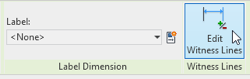
Figure 16–9 Edit Witness Lines command
Look for the blue highlighted edges. These are the currently selected witness line locations. On the left end of the dimensioned wall, it intersects another wall (inside the Exam Room). The vertical edge of the Exam Room wall is the witness line we need to remove.
- Click on the blue highlighted inside edge of the Exam Room to remove that witness line.
- Click in empty space to complete the command (see Figure 16–10).
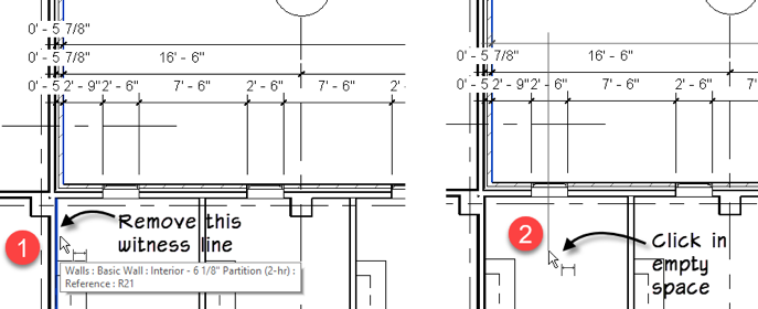
Figure 16–10 Remove a witness line
- Repeat the process for the other two dimension strings and remove the same witness line for each (see Figure 16–11).
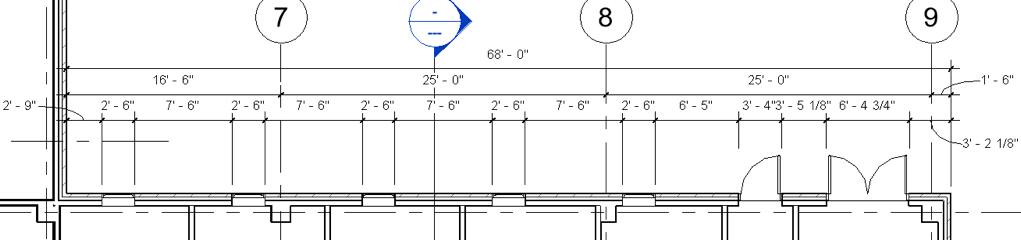
Figure 16–11 Edit the other dimension strings
Complete any other adjustments to the dimensions that you wish.
Adding Tags
When we duplicated the view, we got only the model, no tags or dimensions. It might be nice to have the room tags and perhaps some other tags like door or window tags as well. Tag All Not Tagged is a quick way to achieve this.
- On the Annotate tab, click the Tag All button (see Figure 16–12).
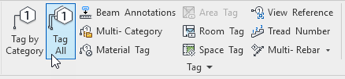
Figure 16–12 The Tag All Not Tagged tool
Let’s start with the Room Tags. We added the rooms in an earlier exercise. It is important that you realize that rooms, even though invisible, are part of the model just like walls, doors and windows. Therefore, do not use the Room tool to add more rooms. This will create redundant rooms. Instead, simply tag the rooms again in this view.
- In the “tag All Not Tagged” dialog, check the Room Tags box and then click OK (see Figure 16–13).

Figure 16–13 Add all room tags
Room tags will appear for all rooms in the view. The best part is, if you rename or renumber a room here in this view, it will automatically be reflected in the other views as well, like the original Level 1 plan or a section view. Give it a try!
- Run the Tag All command again.
You can check more than one box.
- Check both Door Tags and Window Tags and then click OK (see Figure 16–14).

Figure 16–14 Tag all doors and windows
Feel free to continue adding other tags and dimensions.


