Add building core - Exercise
Task 1: Copy/monitor elevator shaft and slabs
During this task we are going to step through a workflow for copying walls and floors from the architect's model and copy them over to the structural model to be used for the structural analysis.
- Open the project STRUCTURAL (Creating Super-structure Start).rvt.
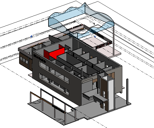
- Open the default {3D} view.
- From the Collaborate ribbon, select Copy/Monitor, then Select Link.
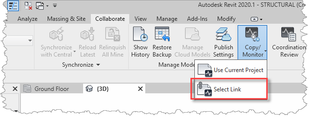
- Select architectural link file (ARCHITECTURE.rvt).
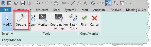
- From the Copy/Monitor ribbon, select Options.
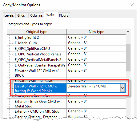
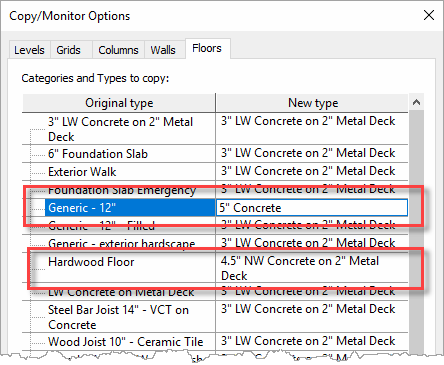
- In the Copy/Monitor Options dialog, switch to the Walls tab and select Elevator Wall – 12" CMU w furring & wood Planks in the Original type list and map it to Elevator Wall – 12" CMU in the New type list.
- Then, switch to the Floors tab and select Generic 12" and Hardwood Floor in the Original type list and map them to 5" Concrete and 4.5" NW Concrete on 2" Metal Deck in the New type list, respectively.
- OK the dialog to save the options.
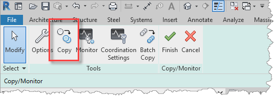
- Select Copy from the Copy/Monitor ribbon.
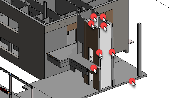
- In no order, select the following wall (4) and floor (2) objects from the linked architectural model.
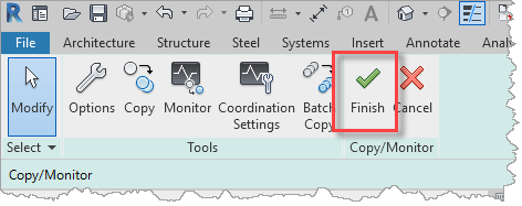
- Once the objects have been copied over, close the Copy/Monitor process with the big green Finish tick on the ribbon.
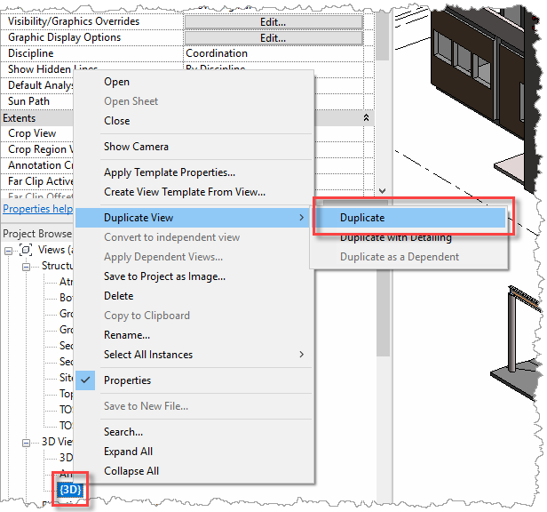
- With the new objects drawn over the existing ones, they are hard to differentiate. Therefore, create a new view that only displays the objects in the structural model without any of the objects in the ARCHITECTURAL and MEP linked files. Right-click on the {3D} view in the Project Browser and select Duplicate View, then Duplicate.
- Rename the view to 3D Structural Only.
- Then open the Visibility/Graphics Overrides dialog to disable the display of the ARCHITECTURAL and MEP links in the new view.

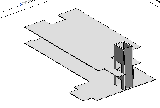
- The view now only displays the objects in the structural model.
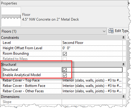
- For these new walls and floors to be considered for structural analysis, they need to have their Structural property enable, so for these objects, enable Structural in the Properties Palette (this should also automatically check the Enable Analytical Model property).
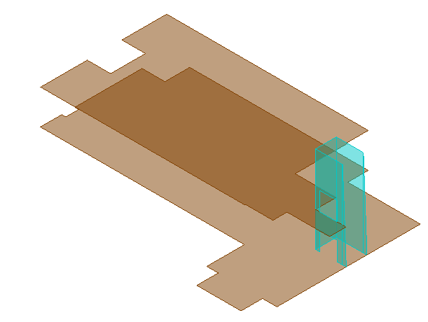
- Open the Analytical Model view to review the progress of the analytical model.
- Save the project so that it can be used in the next objective which will be to cut holes in the floor slabs to accommodate the elevator mechanism and a duct riser.
Task 2: Cut holes in slabs
Whilst we have got the overall size of the floor slabs from the architect there are a couple of significant openings that need to be made in the floors that will impact the structural analysis calculations, therefore it is necessary to cut some holes in the new slabs.
The first hole we shall cut is in the ground floor slab underneath the elevator shaft, to accommodate the elevator pit and the second hole will be in the second-floor slab to accommodate the duct risers.
- Continue with the model saved in the previous task.
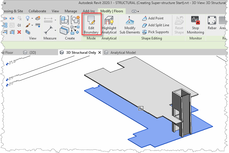
- Open the default 3D Structural Only view, select the ground floor slab, and select Edit Boundary from the Modify | Floors ribbon.
- Open the Ground Floor plan.
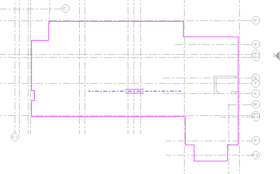
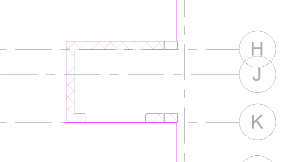
- Zoom into the area around the elevator shaft.
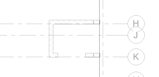
- Trace around the elevator shaft with a sketch line.
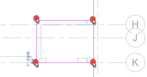
- Use the Split Element tool (from the ribbon) to cut out the segment in the original slab perimeter.
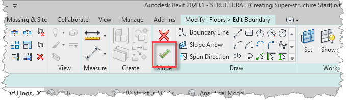
- Complete the Edit Boundary process with the big green tick on the ribbon.
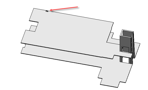
- Open the 3D Structural Only view to review the opening under the elevator shaft.
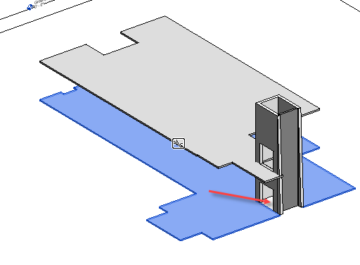
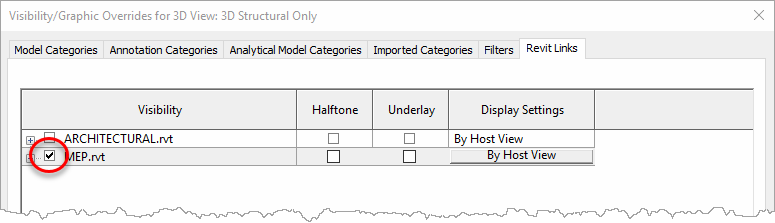
- Next, we shall review where a hole is required to provide a service riser for the ducts. Either create a new view that displays just the current structural model and the linked MEP model, or temporarily display the MEP link in the 3D Structural Only view. To do this, use Visibility/Graphics Overrides and enable the display in the Revit Links tab.
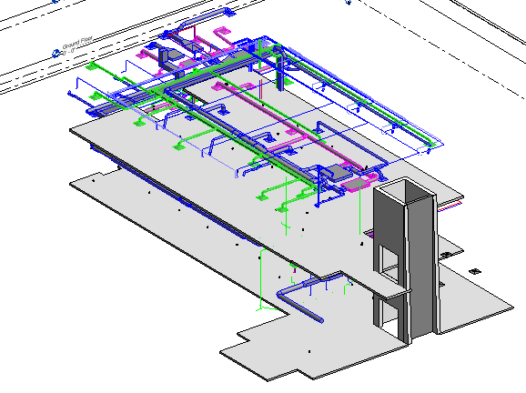
- You model should look something like this.
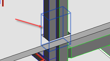
- Spin the model around and zoom into the area that the ducts pass through the second-floor slab.
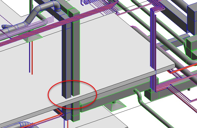
- We shall use this as another example of how to cut a hole into the slab. This is best done in a plan, so open the Second Floor plan view, and zoom into the area of the duct risers (close to grid intersection D6).
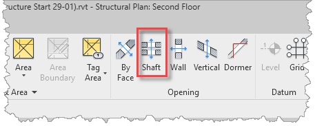
- From the Architecture ribbon, select Shaft from the Opening panel.
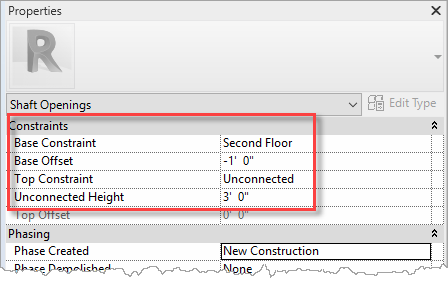
- For the vertical location of the shaft open, use the Properties Palette to specify the Base Constraint (e.g. Second Floor with an offset of -1' 0") and a Top Constraint (e.g. Unconstrained with an Unconnected Height of 3' 0").
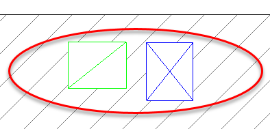
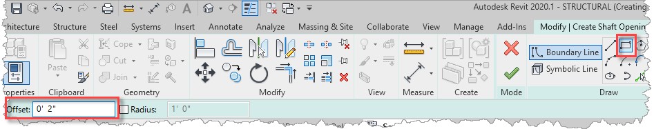
- For defining the opening outline, select the Rectangle option and specify an Offset (e.g. 2").
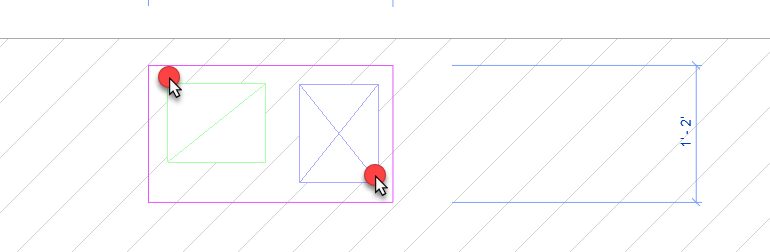
- Draw a rectangle defined by the corner extents of the ducts, as illustrated (unfortunately, the cursor does not snap to the duct geometry, but the actual opening size can be updated to a precise size later through the active dimensions). The opening will be expanded by the specified offset to provide a clearance between the ducts and the slab.
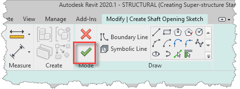
- To actually cut the Shaft Opening, use the Finish Edit Mode button on the ribbon.
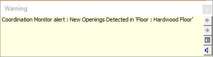
- Since we Copy/Monitored the slab from the architectural link, you will see a Coordination Monitor alert that has detected a change in the slab. This should prompt the structural engineer to have a coordination discussion with the architect about the required openings in slab.
- Back in the 3D Structural Only view, we can now see the hole in the slab where the ducts pass through.
- Using the Visibility/Graphics Overrides dialog, hide the display of the MEP model in the view.
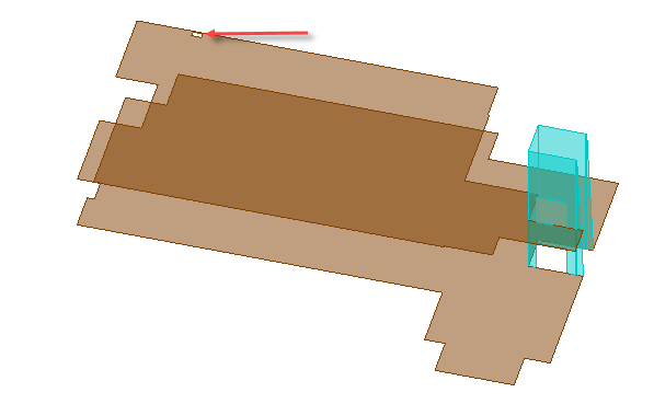
- Switching to the Analytical Model view, the opening can also be seen in the analytical representation.
- Save the project so that it can be used in the next objective which will be to add a slab edge to the ground floor slab.
Task 3: Add slab edge
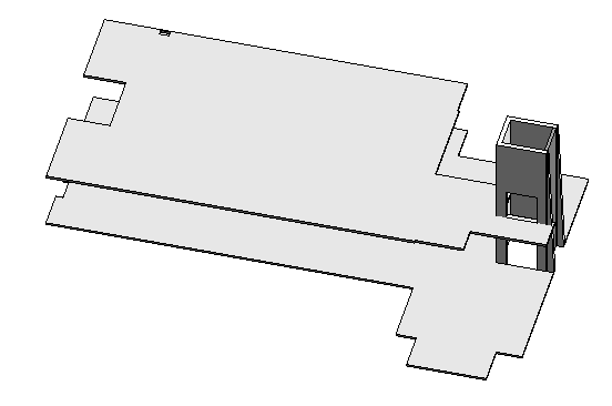
To add additional strength to the ground floor slab, we shall thicken its perimeter edge using the Slab Edge command.
- Continue with the model saved in the previous task.
- Open the default 3D Structural Only view.
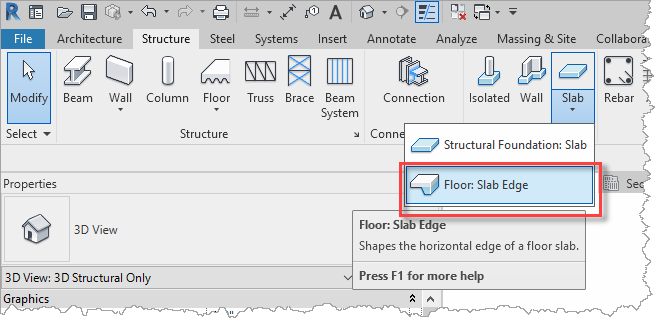
- From the Structure ribbon, select Slab, then Floor: Slab Edge.
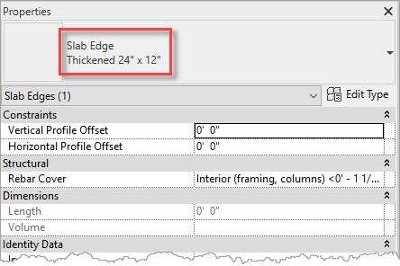
- First select the required Slab Edge of Thickened 24" x 12" in the Properties palette.
- Simply select one of the edges of slab whilst holding down the Tab key.
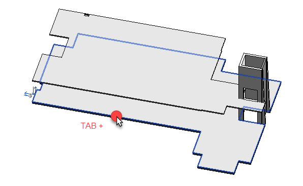
- The command will apply the slab edge to the whole perimeter of the slab, which is easier to appreciate from the underside using the Hidden Visual Style.

- Optionally, save or quit the project as there is a predefined project saved for the next task.


