00:00
MARTHA HOLLOWELL ORCUTT: Performing steel design
00:03
In this video, we will perform steel design
00:05
for a selected group of bars on the roof.
00:09
I'm working in robot structural analysis
00:11
using the small Medical Center model that
00:13
was linked from Revit.
00:15
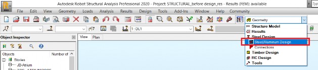
The easiest way to perform structural design and robot
00:18
is to use a predefined screen layout steel aluminum design.
00:23
In the standard toolbar, expand the layouts dropdown list
00:27
and select steel design, and then steel aluminum design.
00:32
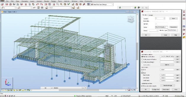
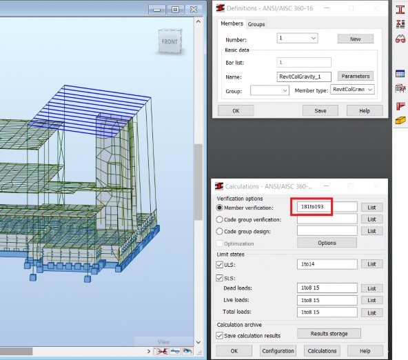
This opens the definitions and calculation dialog boxes along
00:37
with the structural model toolbar on the right.
00:40
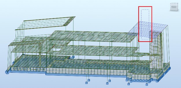
First I want to select the beams I want to modify
00:43
and I'm going to choose the rafters on the roof
00:45
of the lobby of the building.
00:47
I want to edit the steel design parameters
00:49
for the active design code of the predefined beam type.
00:53
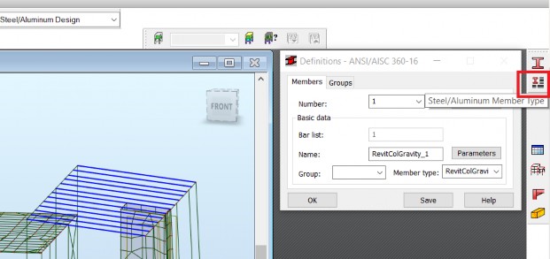
In the structure model toolbar, I'm
00:56
selecting steel aluminum design member type.
00:59
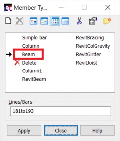
This opens a member type dialog box,
01:02
where I can update the member definition parameters.
01:05
I'm going to select the beam type
01:07
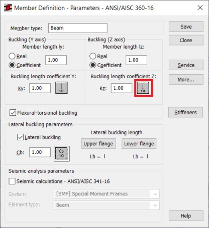
and this opens the member definition parameters dialog
01:10
box specifically for beams.
01:13
I'm going to change the buckling parameters about the z axis
01:17
to include the intermediary bracings that
01:19
are not defined in this model.
01:21
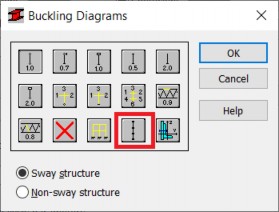
I'm clicking the button to bring up the buckling diagrams dialog
01:24
box, where I'm selecting the internal bracing button.
01:28
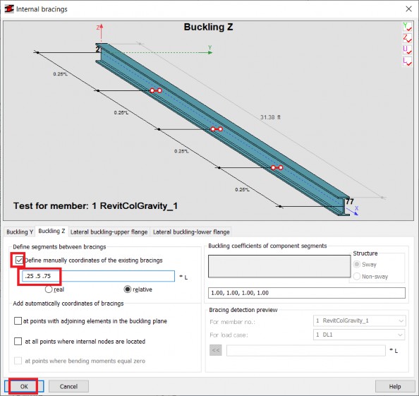
In the internal bracing dialog box,
01:30
I'm defining manually the relative coordinates of three
01:34
bracings along these beams.
01:38
The coordinates are displayed in the graphical preview.
01:43
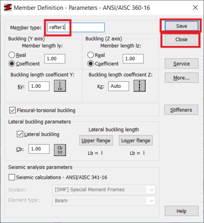
After this modification, we would
01:45
like to save the parameters.
01:47
In the member definition dialog box, click Save.
01:51
As you can see it's not possible to overwrite
01:54
the predefined beam member definition.
01:57
So I'll change the name to rafter 1 and then
02:00
Save and Close the dialog box.
02:06
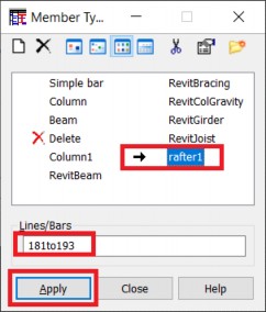
You can see the rafter 1 type was added to the list.
02:09
The selected bars are noted in the lines bars section.
02:13
And selecting apply assigns a rafter 1 type
02:16
to the selected bars.
02:18
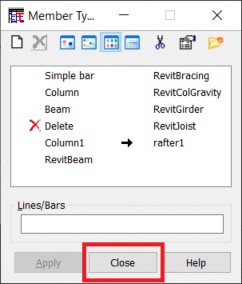
Will close that dialog box too.
02:21
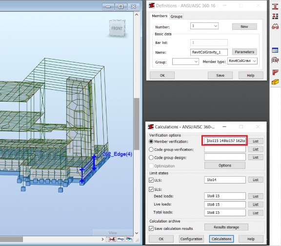
Now, we want to set up calculations for the same bars.
02:25
I'm going to reselect the rafters.
02:30
And in the calculations dialog box,
02:33
we're going to activate member verification
02:35
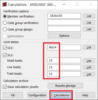
for the selected list to bars and then under limit states.
02:40
I'm going to click the list beside the ultimate limit state
02:45
This opens the load case selection dialog box.
02:48
In the combinations tab, we can select
02:51
all the ULS combinations.
02:55
And click the two up arrows to apply it to the bars.
03:02
Then under serviceability load states,
03:05
I'm going to change the list for each type of load
03:08
leaving only the combination of 15.
03:12
Now you're ready to run calculations
03:14
for member verification.
03:17
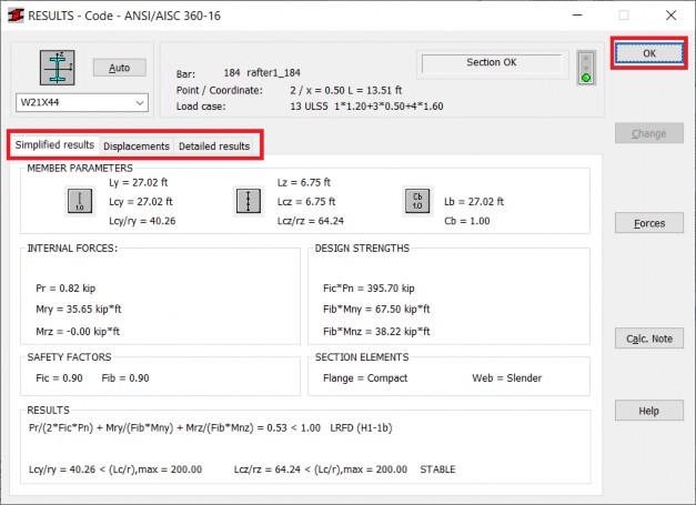
This results in the list of verified members
03:20
with a brief information on the status of calculations
03:24
containing design combination ratio and member slenderness.
03:29
Selecting specific members results
03:31
and opening the window with more detailed information containing
03:35
design forces and moments design code formulas and references.
03:42
As the ratio for these members is close to 0.5,
03:45
we need to search for a more efficient section.
03:48
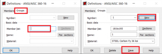
First-- we'll define a design group.
03:51
In the definitions dialog box, I'm clicking on the Groups tab.
03:55
When I click in the member list edit box,
03:57
it applies the selected bars.
03:60
Beside number, I'm going to click New and the number 1
04:05
Under the name I'm going to click rafters and then click
04:10
Now I can search for the sections.
04:13
Beside the member list, I click the sections button.
04:16
In the selection of sections dialog box,
04:19
I can choose from different bar shapes.
04:21
If no specific bar shape is selected,
04:24
robot will search for any of the W sections.
04:27
I'm going to click OK to go with the default.
04:30
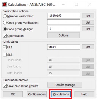
Next, I'm going to run the calculations
04:32
for group 1 defined before.
04:35
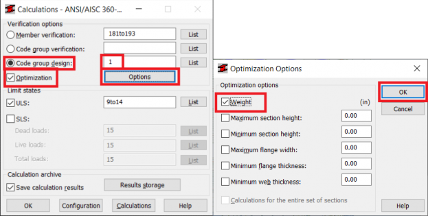
In the calculations dialog box, click code group design
04:42
Then I'm going to click the Options button.
04:44
And in the optimization dialog box,
04:46
I'm going to select wait and click OK.
04:51
In the code group design edit box, I'm going to type 1
04:54
for the group defined earlier and click calculations.
04:58
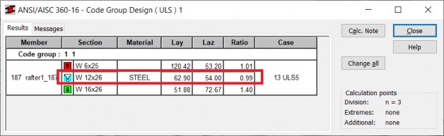
The displayed windows shows the optimum section
05:01
with the blue exclamation sign.
05:04
The optimum section is W 12 by 26
05:08
while the original section in these bars is a W 21 by 44.
05:13
The efficiency ratio for the optimum section
05:15
is 99, an increase from 0.53.
05:20
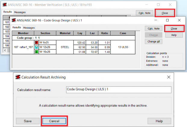
Click on the optimum section to review the results dialog box
05:26
Now let's click change all.
05:29
This replaces the original section with the optimum one.
05:33
An alert box reminds you that this automatically
05:36
changes the status of results from available to out of date.
05:41
And you can see this also up in the title bar.
05:44
This is why it's necessary to rerun
05:47
the calculations of the model.
05:49
In the standard toolbar, click calculations.
05:53
The model is regenerated after the update
05:56
and then the finite element analysis is performed.
05:60
The change of sections for bars can
06:02
result in a different distribution of internal forces
06:05
and moments in the model.
06:07
So after recalculation, it's necessary to perform at least
06:11
the code group verification for group 1.
06:15
In the calculations dialog box, select code group verification
06:19
type in 1 and click calculations.
06:28
Notice that after the recalculation,
06:30
the efficiency ratio has changed from 0.99 to 0.93.
06:35
This is still acceptable.
06:38
You are now ready to continue design and analysis