Add columns and beams - Exercise
During these tasks, we shall continue the development of the building super-structure, with a focus on adding steel columns and beams.
Task 1: Adding columns
During this task we are going to step through a workflow for adding a steel frame of columns and beams to the structural model to be used for the structural analysis.
- Open the project STRUCTURAL (Creating Super-structure Columns & Beams Start).rvt.
- Open the Ground Floor view.
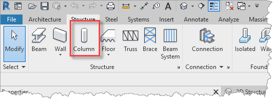
- From the Structure ribbon, select Column.
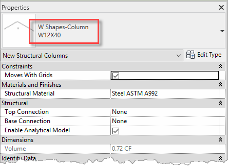
- In the Properties palette, select the column shape W12x40.
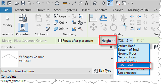
- In the Options bar, select Height and the TOS – Roof, so that the columns will be placed on the current level (Ground Floor) and extend up the roof.
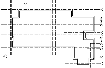
- Place columns by hovering over the grid intersections and confirm the position with a mouse- click when the grid lines are highlighted, for example.
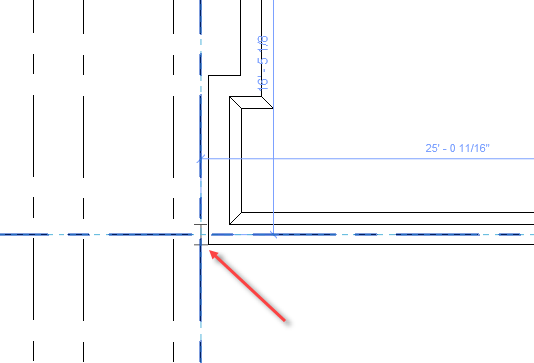
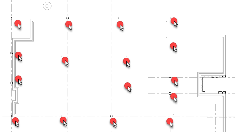
- Continue placing the columns on the floor and use the Space Bar to rotate the columns around to adjust their orientation. In this model the column positions seem pretty random, but if you want to follow closely, these are the intended positions (notice that the underlying slab and the grid lines have been set to halftone for clarity (to do this, select and right-click on one, select Override Graphics in View, then select By Category, and check Halftone in the View Specific Category Graphics dialog).
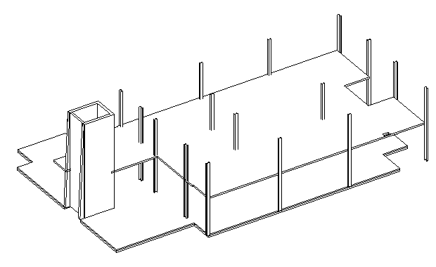
- Open the 3D Structural Only view to see the columns in 3D.
- Save the project so that it can be used in the next objective which will be to add steel beams in between the columns.
Task 2: Adding beams
Once the columns have been added, we can then add the individual beams in between them.
- Continue with the model saved in the previous task.
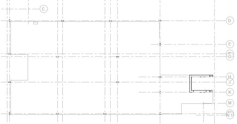
- Open the TOS – Second Floor view, which only contains structural objects. Also, the slabs and grids have been set to halftone for easier identification of the column locations.
- From the Structure ribbon, select Beam.

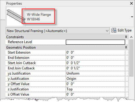
- In the Properties palette, select the W-Wide Flange W18x46 steel shape.
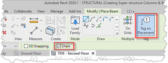
- For frame's outer beams, set the Chain option in the Options Bar so that the start of next beams picks up from the end of the previously placed beam. Also, to automatically annotate each of the beams as they are inserted, enable Tag on Placement in the ribbon.
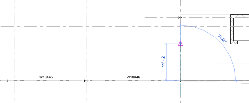
- Simply snap onto each of the columns to add the beams.
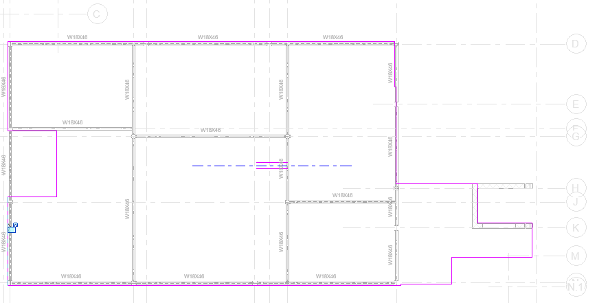
- Complete the framing structure as follows, as switch to Fine Level of detail for more clarity on the positions and sizes of the beams. We can also see that some beams are shown in hidden line style and are hence underneath and supporting the second-floor slab, whereas the beams on the left and top edge are not providing any support.

- This is easily rectified by editing the boundary of the slab.
- Switching to the 3D Structure Only view, we can see how the model is progressing, with the new beams added underneath the second-floor slab.
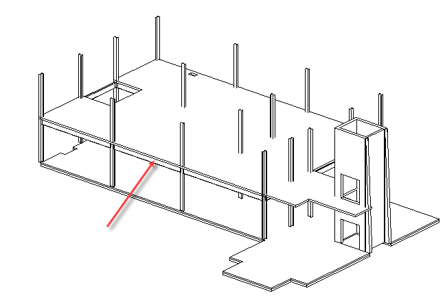
- Next, we shall copy these beams from the underside of the second-floor slab to the roof level. To do this, select one of the beams, right-click and from the menu, select Select All Instances, then select In Entire Project.

- Next, copy the selected to the clipboard, either with a simple Ctrl+C or using the Copy tool on the Modify | Structural Framing ribbon.
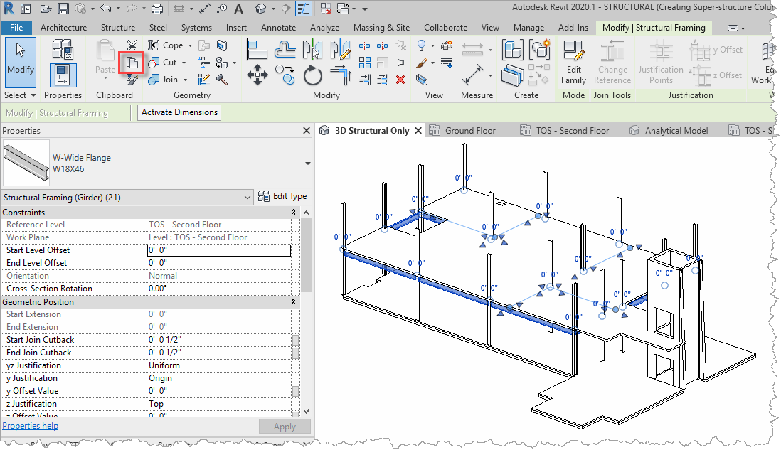
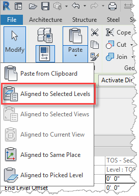
- Select Paste and Aligned to Selected Levels from the Modify | Structural Framing ribbon.
- In the Select Levels dialog, select TOS – Roof.
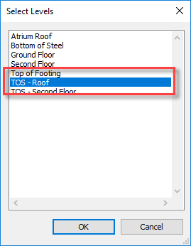
- Select OK to close the dialog and the new beams will be copied up to the roof level.
- Save the project so that it can be used in the next objective, which will be to add roof joists between beams on the roof level.
Task 3: Adding beam systems
Our next task is to try out the steps to automatically place an array of beams using the Beam Systems functionality, to represent the roof joists spanning beams.
- Continue with the model saved in the previous task.
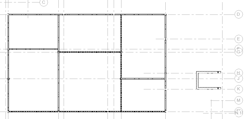
- Open the TOS – Roof view in which the only contains structural objects and the grids have been set to halftone for easier identification of the column and beam locations.
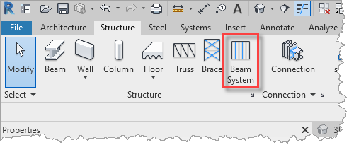
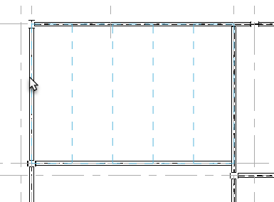
- From the Structure ribbon, select Beam System.
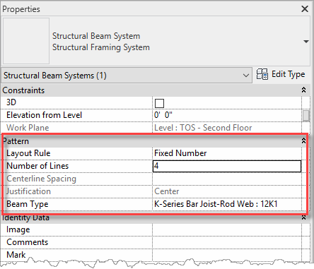
- In the Properties palette, set the Layout Rule to Fixed Number, the Number of Lines to 4, and set the Beam Type to K-Series Bar Joist-Rob Web : 12K1.
- As you hover the cursor over a beam, the command will automatically preview the beam layout in the adjacent framing section.
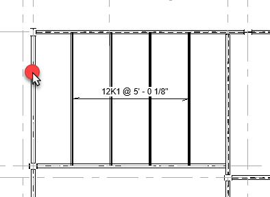
- Select the beam and the beam system will be inserted into the model.
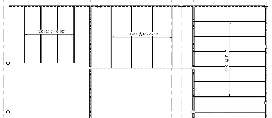
- Repeat this procedure to add beam systems to some of the other framing sections. Try changing the number of beams and alternative joists.
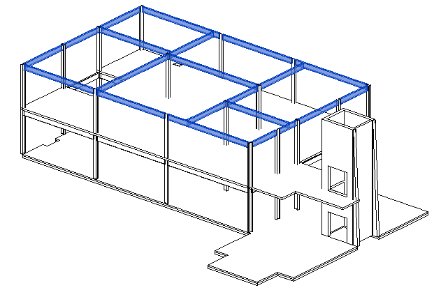
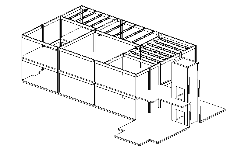
- Switch to the 3D Structure Only view to review the model progression in 3D.
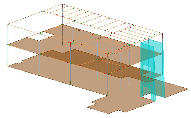
- Switch to the Analytical Model view to review the model that will be used for the structural analysis.
- Optionally, save or quit the project as there is a predefined project for the next task.


