Add braces - Exercise
During these tasks, we shall continue the development of the building super-structure, with a focus on adding some diagonal braces.
Task 1: Creating a framing elevation
During this task, we are going to step through a workflow for adding diagonal braces the structural model to be used for the structural analysis.
- Open the project STRUCTURAL (Creating Super-structure Braces Start).rvt.
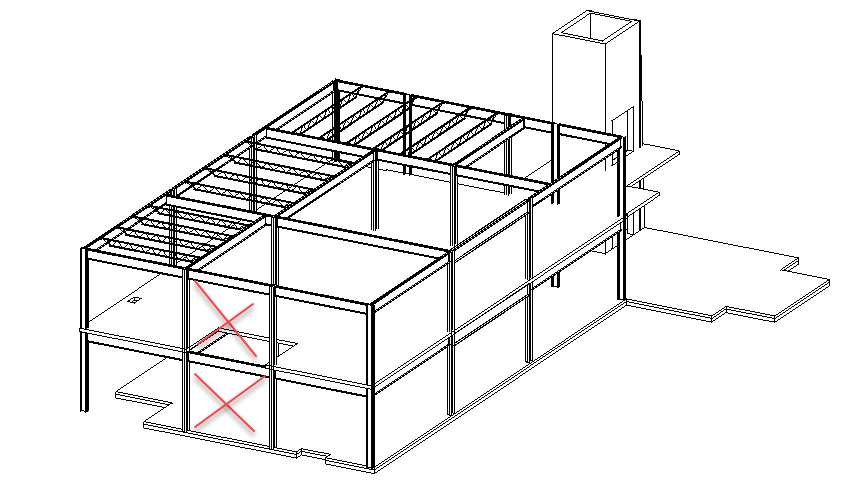
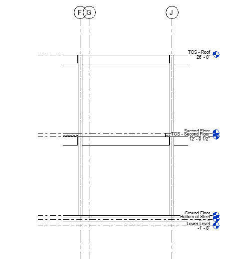
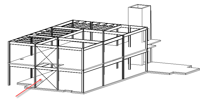
- Open the 3D Structural Only view. The intention is to add cross braces to the two framing sections illustrated below.
- To place the braces, we will set up a framing elevation. To add a Framing Elevation, open one of the floor plans, such as the Second Floor view.
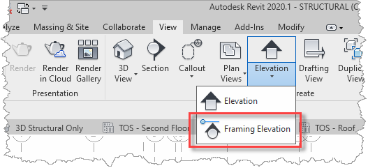
- From the View ribbon, select Elevation and then select Framing Elevation.
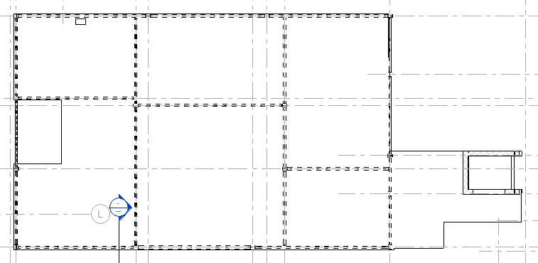
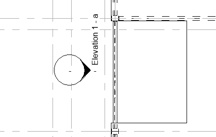
- Hover over the grid line under the middle beam at the left-hand end of the frame, as you do so an elevation tag will preview the view direction for the elevation.
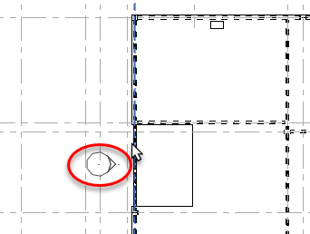
- When it is point towards the frame, select the grid line. The elevation tag will be inserted into the plan and will be updating to include the generated elevation view name (e.g. Elevation 1-a in the example below).
- Locate the new view in the Project Browser.
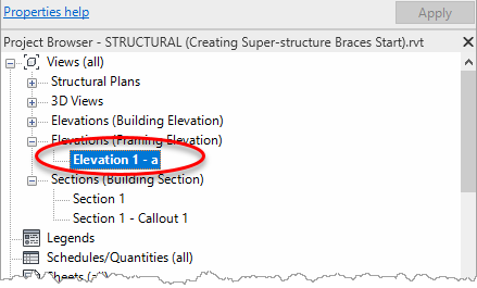
- Open the view to reveal an elevation of the steel frame clipped to the length of the selected grid line.
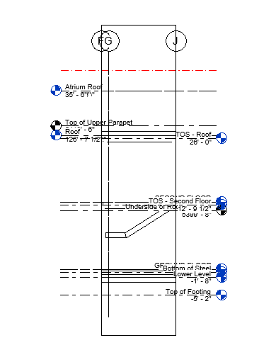
- This elevation needs a bit of a tidy – perhaps expand the crop box either side and reduce the height.
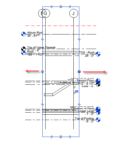
- Use the Visibility/Graphics Overrides dialog to switch off the display of the ARCHITECTURAL and MEP links and the crop box, reduce the view scale to ¼" to 1'-0" to reduce the size of the level header text, and perhaps switch to Fine Detail Level for clarity (these settings can all be saved in a View Template and applied to other framing elevations). The elevation should now look more like this, and we can easily make out the steel beams and columns.
Task 2: Adding braces
With the framing elevation set up, it can be used for adding the diagonal braces to the model.
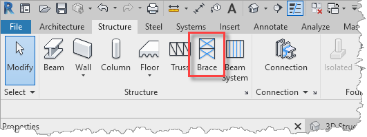
- To insert the braces, select Brace from the Structure ribbon.
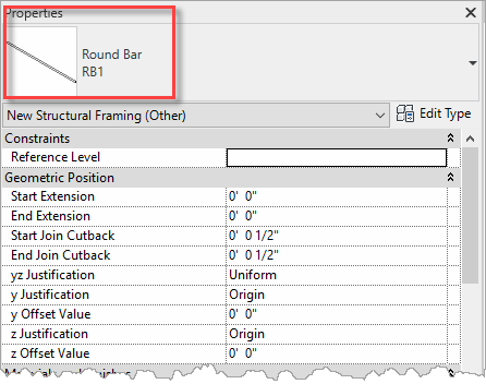
- In the Properties palette, choose the Round Bar RB1 framing type.
- Then, place the braces by snapping to the framing geometry, for example.
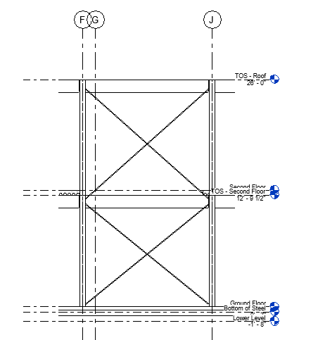
- Opening the 3D Structural Only view, the braces can be seen in the updated model.
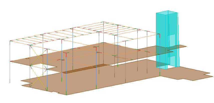
- Likewise, opening the Analytical Model view, the braces can be seen in the updated analytical model.
- Optionally, save or quit the project as there is a predefined project saved for the next tasks.


