Modeling cable tray vertically

Model a cable tray vertically on a wall - Exercise

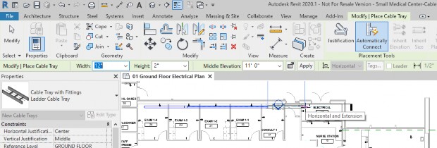
  1. Open the Small Medical Center-Cable Tray Vertical.rvt project. You are in the in the 01 Ground Floor Electrical Plan view. We are going to add cable try down the edge of the back wall and into the Electrical Room.
  2. In the Systems tab > Electrical panel, click Cable Tray.
  3. In the Type Selector, select Cable Tray with Fittings: Ladder Cable Tray.
  4. In the Options Bar, set up the size to Width: 8", Height 2", and Middle Elevation 11'-0".
  5. Start modeling the cable tray in Exam 1-4 and draw it into the next exam room.
  6. In the Options Bar, change the Width to 10".
  7. Draw it down into the Consulting Room and change the width to 12", as shown below. Notice how the fittings between the sizes are automatically applied.

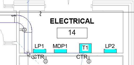
  8. Draw the cable tray into the Electrical Room and turn the corner and draw it close to the back wall, as shown below.

  9. In the Options Bar, change the Middle Elevation to 2”. Move into the view and then back to the Options Bar and click Apply. This sends the cable tray down and ends the command run of cable tray.
  10. Press <Esc> to completely end the command.
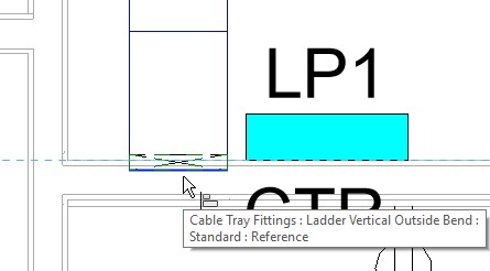
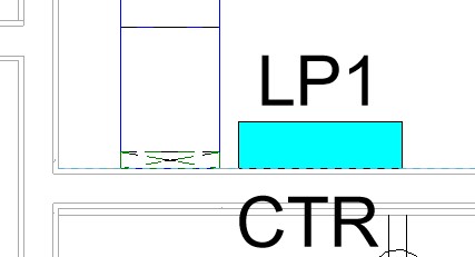
  11. Zoom in and align the back of the cable tray to the wall, as shown below, before and after.


    Before


    After

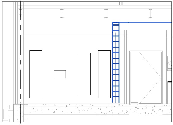
  12. Open Electrical Room South Wall (Panels) Section. You can see the cable tray vertically down the wall, as shown below.

  13. If you want to move it over, you can drag it or use the move command to get it into place.
Was this information helpful?