Creating and updating electrical circuits - Exercise
In this practice, you will investigate existing electrical circuits in a project and create new circuits in preparation for creating wire diagrams.
Task 1: Review electrical circuit tags and filters
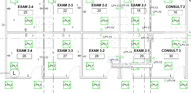
- Open the Small Medical Center-Circuit-2021.rvt project. The Ground Floor Electrical Plan view displays. This plan view shows lights and power.
- Zoom in and identify tags that display the circuit number on the electrical devices and light fixtures, as shown below.
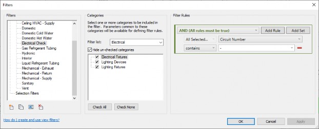
- A filter is applied to the view that identifies elements that have a circuit number. Type VV to open the Visibility Graphic Overrides dialog box and select the Filters tab. The Filter is called Electrical Check.
- Click Edit/New….
- In the Filters dialog box, verify that Electrical Check is selected, Set the Filter List to Electrical and check Hide un-checked categories. This filter is applied to Electrical Fixture, Lighting Devices, and Lighting Fixture. The Filter Rule is that there is a Circuit Number and it includes a hyphen in it, as shown below.
- Click OK to close the dialog boxes. This filter is helpful when you are building your electrical circuits.
Task 2: Create and update circuits
- In the Project Browser in the Electrical>Power>Floor Plans group, right-click on Ground Floor Electrical Plan and select Duplicate View>Duplicate. This duplicates the view but does not include any annotation elements.
- Rename the view Ground Floor Electrical Devices Plan.
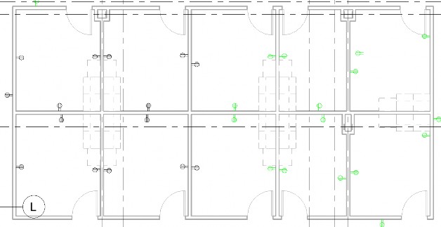
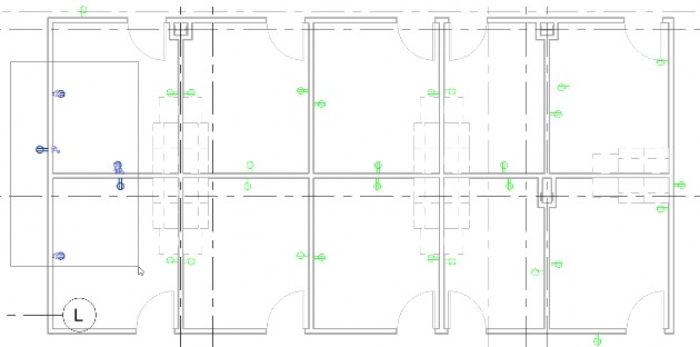
- Select one of the light fixtures and type VH for View Hide. The visibility of the category is turned off in the view.
- Repeat the same process with the Switches. The remaining view just displays the outlets, as shown below.
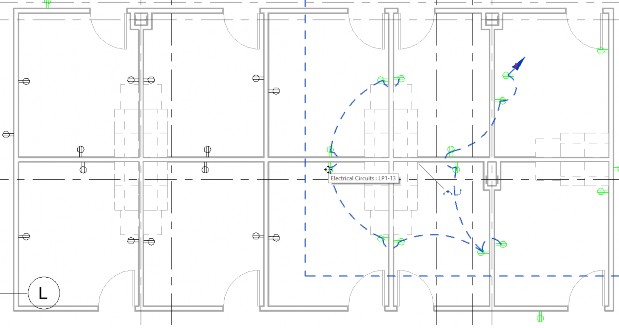
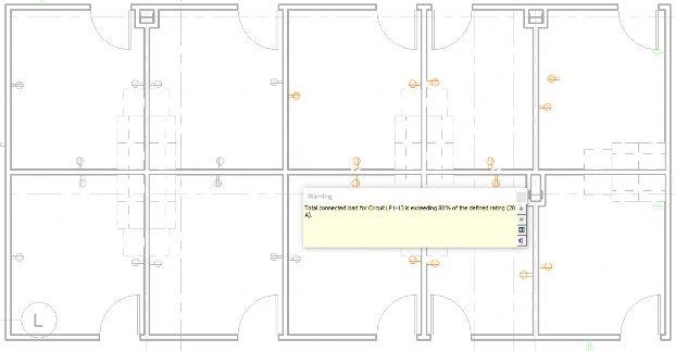
- Hover over one of the outlets is connected to a circuit and press <Tab> until you see the circuit and then click to select it. The temporary wiring also displays so you can see which outlets are connected, as shown below.
- In the Modify | Electrical Circuits tab > System Tools panel, click Edit Circuit.
- In the Edit Circuit tab, the Add to Circuit tool is selected. Click on one the outlets that is not in the circuit.
- A warning displays, as shown below. This circuit is already full. Click Cancel Editing Circuit.
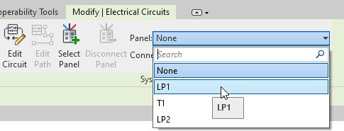
- Select one of the outlets that is not in a circuit. In the Modify | Electrical Fixtures tab > Create Systems panel, click Power.
- In the Modify | Electrical Circuits tab, select the Panel LP1, as shown below.
- Click Edit Circuit.
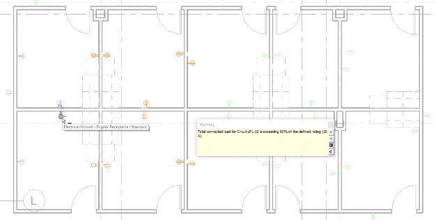
- In the Edit Circuit tab, the Add to Circuit tool is selected. Click on other outlets nearby and add them to the circuit. When you get to the warning, as shown below, click Remove from Circuit and remove the extra outlet.
- Click Finish Editing Circuit and the new circuit is created. The outlets turn green now because the filter is satisfied.
- Use a window selection to select the rest of the outlets that are still uncircuited, as shown below.
- In the Modify | Electrical Fixtures tab> Create Systems panel, click Power. This time the LP1 is automatically selected and all the outlets are placed in the circuit.
- Save the project.


