00:01
NARRATOR: Reviewing existing duct and piping systems
00:06
In this video, we're going to review a little bit about duct
00:09
and piping systems and how you assign elements to systems.
00:14
Then we're going to take a look at the existing duct and piping
00:17
systems that come with Revit.
00:20
Duct and piping systems are created in two different ways.
00:24
First you run duct your pipe from an element with connectors
00:28
and it automatically creates a system.
00:31
Second you can assign elements to a system
00:34
and later add the connectors.
00:37
I've opened the Small Medical Center project in a 3D view,
00:41
and I'm going to zoom in on the tankless hot water heater
00:44
that I placed on the outside of the building.
00:47
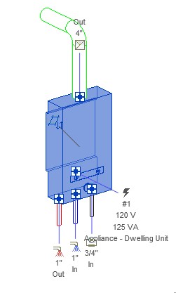
When I select the hot water heater,
00:49
you can see that there are connectors that are assigned
00:52
to different types of systems.
00:54
I've also added pipes and ducts.
00:57
They take on the correct system type and color.
01:07
When I click on one of the pipes and look at properties,
01:11
you can see that the system type is specified.
01:24
And here's the duct.
01:29
Another way of working is to select the fixtures
01:32
and assign them to a system without having
01:35
any connecting elements.
01:37
So let's take a look at that in plan.
01:42
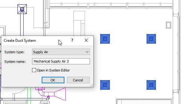
In the O1 ground floor HVAC plan on the far right
01:46
are for air terminals that do not yet have a system.
01:50
They show up as black.
01:52
I'm going to select them and create a duct system.
01:58
So in the Modified air terminals tab I'm going to click Duct.
02:06
And I'm going to accept the existing name and click OK.
02:15
And then you can see that they show up as blue.
02:20
The reason is that they are supply air terminals,
02:23
and supply air systems have been assigned
02:25
the blue color in their type properties by default.
02:32
Now let's look at the default duct and piping systems
02:35
that come with the mechanical template.
02:37
That's all that's used in this project so far.
02:41
In the project browser, I'm expanding the family's list.
02:47
And you can see that along with various types of elements,
02:52
including things like air terminals, duct fittings,
02:58
and flex pipes, there are families for duct systems
03:07
and for piping systems.
03:18
So our duct systems include exhaust air, return air,
03:26
And the piping systems include domestic cold and hot water,
03:30
a variety of fire protection systems,
03:34
hydronic supply and return, one called other sanitary,
03:43
Now let's take a look at what is set in a system type.
03:48
I'm selecting the duct system exhaust air
03:52
and right clicking on it and selecting type properties.
03:55
And you can see here the type parameters.
03:58
You have graphic overrides which you
04:01
can select a pattern, color, and weight for the system.
04:05
And you can see here that exhaust air
04:07
systems are set to green.
04:10
For the material, you can set the material for the system,
04:14
but this is more frequently set by duct or pipe type,
04:18
the actual physical elements.
04:20
So in the system it's set by category as you can see here.
04:25
In order to perform calculations,
04:27
ducts and pipes need to be on an appropriate system,
04:31
and you can set the type of calculation here.
04:38
Our identity data includes tight parameters
04:41
you can place in tags and schedules.
04:44
One very helpful option is abbreviations.
04:47
This can be included wasting a tag
04:49
and is also useful when you add the system to a project.
04:54
It's used in the beginning of the assigned name.
04:58
Finally, it's important to also set up your rise drop symbol.
05:08
And I would check with your beam standards
05:10
to see what's needed for each system type.
05:15
These families are hard coded system types
05:18
that come with Revit.
05:19
So any custom system type you create
05:22
has to start by duplicating an existing system.
05:26
A new system type can have any name,
05:28
but its underlying system must be one of these standard types.