Generate documentations and BOMs - Exercise
Task 1: Assign model roles
Before you start assigning model roles to the structural steel elements, you will modify the behavior of the concrete elements so they are not included in the numbering.
- Open the Medical-Center-Documentation.dwg file.
- Select the two concrete slabs.
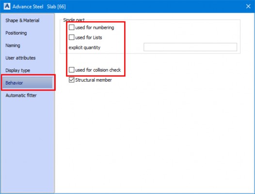
- Right-click in the blank area and click Advance Properties. The Advance Steel Slab dialog box is displayed.
- From the Behavior tab, clear the three check boxes, as shown below.
- Repeat the same thing for the concrete walls.
- From the Home ribbon tab > Project ribbon panel, click Project Explorer > Model Browser, as shown below. The Model Browser window is displayed.
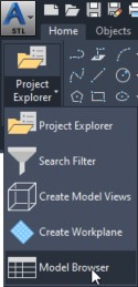
- Right-click on the Object name column and display the Model Role column, as shown below.
- Sort the data in the Model browser window by the Model Role column and then by the Object name column.
- From the top left in the Model browser window, select the Edit properties check box.
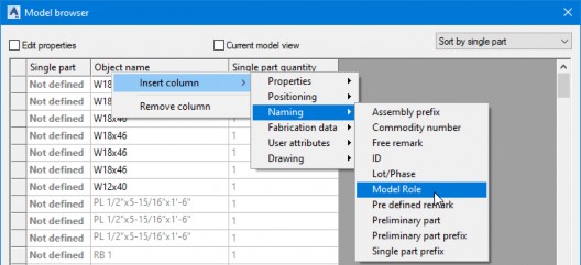
- Select the first row of the W18x46 section.
- Hold down the SHIFT key and click on the Model Role field of the last W18x46 section. The drop- down list is displayed, as shown below.
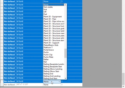
- Type B. The model role of all the selected sections is set to Beam.
- Close the Model browser window.
Task 2: Number structural steel elements
In this section, you will number single parts and assemblies together.
- From the Home ribbon tab > Documents ribbon panel, invoke the Numbering tool. The Numbering dialog box is displayed.
- Select the parameters shown in the figure below.
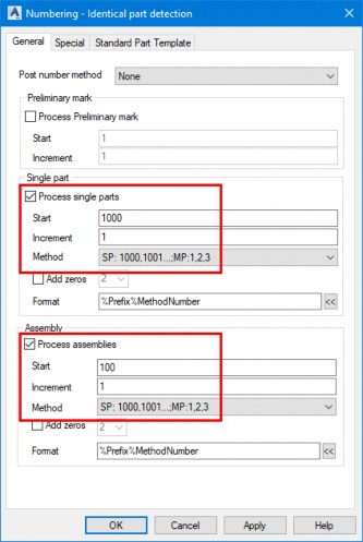
- Click OK in the dialog box. The single parts and assemblies are numbered and the Numbering MP window is displayed with the main part numbering, as shown below.
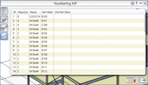
- Review the main part numbering.
- From the categories on the left of this window, click Numbering SP and review the single part numbering, as shown below.
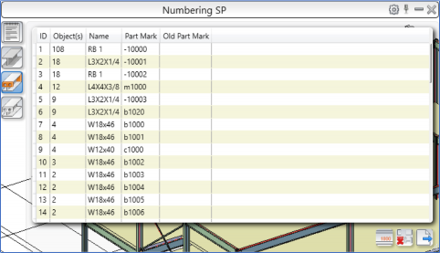
- Close the window.
- Save the model.
Task 3: Configure default settings to generate single part drawings
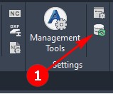
- From the Home ribbon tab > Settings ribbon panel, click Management Tools. The ADVANCE STEEL MANAGEMENT TOOLS window is displayed.
- Click Defaults to display the default settings.
- On the bottom left, select the Use filter check box.
- In the field below the Use filter check box, type Drawing.
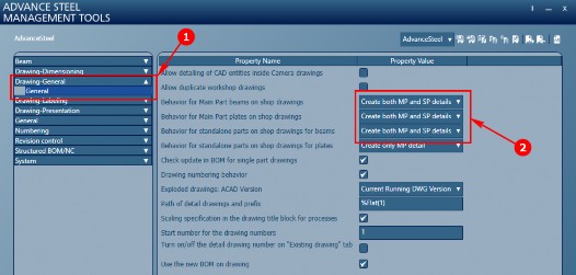
- Click Drawing General > General, labeled as 1 in the figure below.
- From the right pane, select the options to generate both single part and main part drawings, labeled as 2 in the figure below.
- Close the ADVANCE STEEL MANAGEMENT TOOLS window.
- From the Settings ribbon panel, click the Update Defaults button labeled as 1 in the figure below.
Task 4: Generate single part drawings
- From the Home ribbon tab > Projects ribbon panel, click the Project Explorer > Model Browser to display the Model browser window.
- Select all the items that have their model roles as Beam or Column.
- Close the Model browser window.
- From the Home ribbon tab > Documents ribbon panel, click the Drawing Processes button to invoke the Drawing Processes palette.
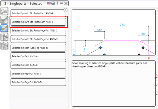
- From the toolbar on the left of the Drawing Processes palette, click the 3 – Singleparts - Selected category.
- Click the second button in this category that shows Selected Sp (w/o Std Parts) Each ANSI-B, as shown below. The Process properties dialog box is displayed.
- Click OK in the Process Properties dialog box. The process of generating single part drawings starts.
Task 5: Generate assembly drawings
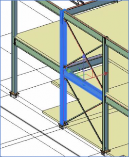
- Select the two sections highlighted in the figure below.
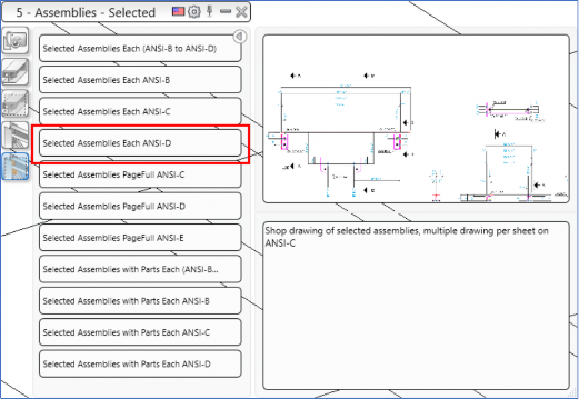
- From the Drawing Processes palette, activate the 5 – Assemblies – Selected category and then click the Selected Assemblies Each ANSI-D tool, as shown below. The Process properties dialog box is displayed.
- Click OK in the Process properties dialog box. The process of generating the assembly drawings of the two selected main parts starts.
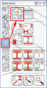
- From the Advance Steel Tool Palette, click the Selection category and invoke the Search filters tool, as shown below. The Advance Steel Search and mark objects dialog box is displayed.
- From the left pane, click the Objects tab.
- From the right pane, select the Steel beam check box.
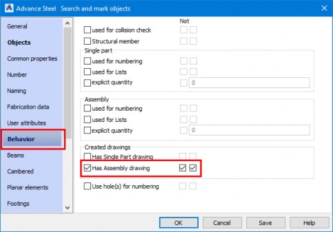
- From the left pane, click the Behavior tab.
- From the right pane, select the check boxes as shown in the following figure.
- Click OK in the dialog box. The sections that do not have their assembly drawings created are highlighted in Red.
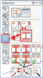
- From the Advance Steel Tool Palette > Selection category, click the Select all marked objects button, as shown below.
- From the Drawing Processes palette, activate the 5 – Assemblies – Selected category and then click the Selected Assemblies Each ANSI-D tool. The Process properties dialog box is displayed.
- Click OK in the Process properties dialog box. The process of generating the assembly drawings of two selected main parts starts.
- Enter RE to regenerate the drawing.
- Save the model.
Task 6: Review the generated drawings
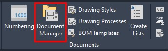
- From the Home ribbon tab > Documents ribbon panel, invoke the Document Manager tool, as shown below. The Document Manager dialog box is displayed.
- From the left pane in the dialog box, expand Details > Up to date and click on any of the drawings, as shown below.
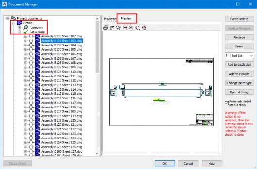
- From the right pane, activate the Preview tab and preview the selected drawing.
- Double-click on any of the assembly drawings – it is opened in its window.
- Review the assembly drawing and then close it to return to the 3D model window.
- Invoke the Document Manager dialog box again and then double-click on any of the part drawings to open it.
- Review the part drawing and then close it to return to the 3D model window.
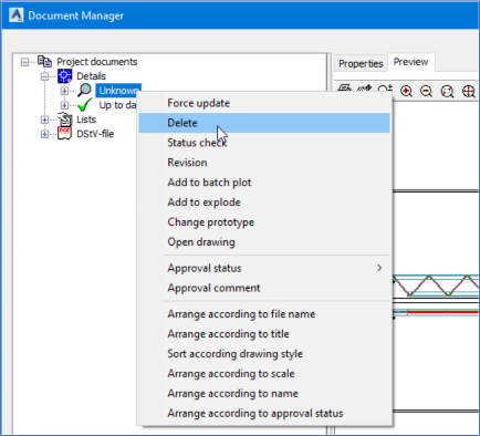
- Invoke the Document Manager dialog box again.
- From the Details category, right-click on the Unknown category and click Delete from the shortcut menu, as shown below.
- Close the Document Manager dialog box. The Document to print or delete or explode dialog box is displayed.
- Click OK in the dialog box.
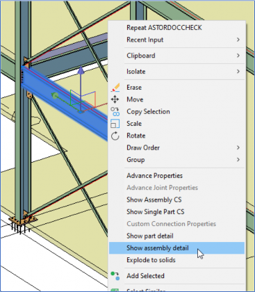
- From the model, click on any beam to select it.
- Right-click on it and click Show assembly detail, as shown below. The assembly drawing of the selected beam is opened in its window.
- Close the drawing to return to the 3D model.
- Similarly, open the part detail of any structural element using the method shown above.
- Press the ESC key to deselect everything.
- Save the model.
Task 7: Generate BOMs
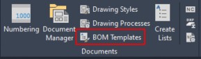
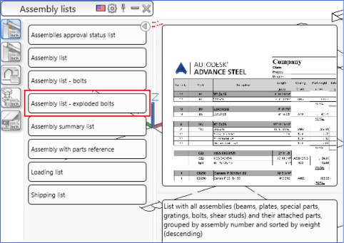
- From the Home ribbon tab > Documents ribbon panel, invoke the BOM Templates tool, as shown below. The BOM Templates palette box is displayed with the Assembly List category active.
- Click the Assembly list – exploded bolts button, as shown below. The process of generating the assembly list with exploded bolts starts.
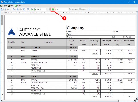
- Once the assembly list is generated, it will open in a new window. Review various pages of the assembly list using the Next page button labeled as 1 in the figure below.
- From the top left in this window, click the Save button and save the BOM in its default location. The BOM is saved in the RDF format file.
- From the top left in this window, click the Export button and export the BOM in the PDF format in its default location.
- Close the window to return to the Advance Steel window.
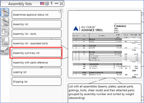
- Similarly, generate the Assembly summary list using the button highlighted in the figure below.
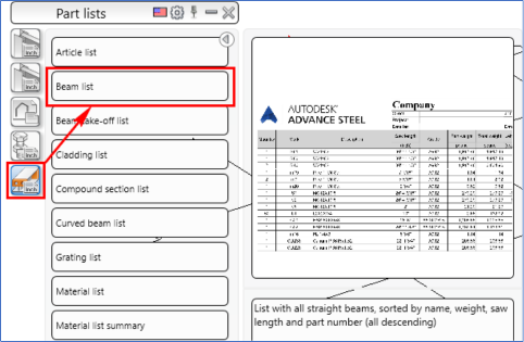
- In the BOM Template palette, click on the last button from the toolbar on the left to invoke the Parts lists category and then click the Beam list button, as shown below.
- Review the beam list and then save and export it.
- Similarly, generate the Material list summary using the button shown in the figure below.
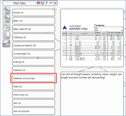
- Save and export the Material list summary.
- Invoke the Document Manager.
- From the left pane, expand the Lists > Up to date category and notice the saved BOMs listed there in the RDF format, as shown below.
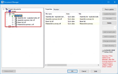
- Close the Document Manager dialog box.
- Save the model.


