00:01
DEEPAK MAINI: The last objective of this course
00:02
is to control the visibility of various structural elements
00:11
As we saw when we imported the structural connections
00:14
from advanced steel into Revit, they
00:16
were displayed at green lines and circles.
00:18
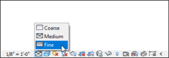
That's because the detail level is set to medium
00:22
by default in the model.
00:24
We are going to learn how we can change the detail level to fine
00:27
so we can see all the connections with the plates
00:31
We are also going to interrogate the Revit model
00:33
and if there's any missing connection,
00:35
we are going to apply that inside Revit
00:38
so we'll learn how to add connections and Revit as well.
00:42
And finally, I'm going to show you
00:44
how we can control the visibility
00:46
of various structural connection elements using the visibility
00:51
Let's get straight into Revit now.
00:54
As you can see in this model, all the imported connections
00:58
are displayed as green lines and circles.
01:00
To change this, I'm going to click on detail level
01:03
and I'm going to change it to fine.
01:10
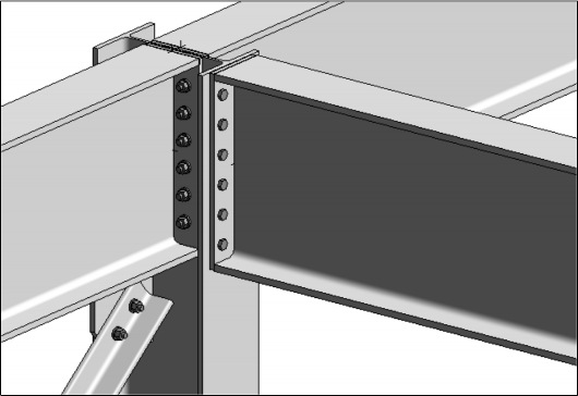
With this, if I never get closer to a connection,
01:15
you will notice that the connection is now
01:16
displayed with the plates and the connecting bolts as well.
01:29
The best part of this workflow is that these connections are
01:32
imported as smart connections.
01:34
And if required, you can modify them inside Revit as well.
01:41
So if I need to modify let's say,
01:42
to this baseplate connection, I can simply click on it
01:45
and then I can override the instance parameter
01:48
by clicking on the Edit option.
01:53
It will display the dialog box which
01:55
is exactly similar to what we saw in advanced steel
01:58
with the same categories and the same tabs in those categories.
02:07
Although I would recommend not to modify these parameters here
02:10
in Revit because then your Revit model
02:13
is different from your detail model and advanced steel.
02:18
Now if I navigate here, I can see that the bridging joint
02:22
here was not imported.
02:24
This is where I'm going to show you how you can create joints
02:26
within Revit as well.
02:28
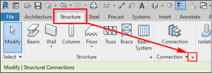
For that, I'll go to the structure ribbon tab.
02:33
And in the connection ribbon panel,
02:35
I will first load the connection type that I want to add.
02:41
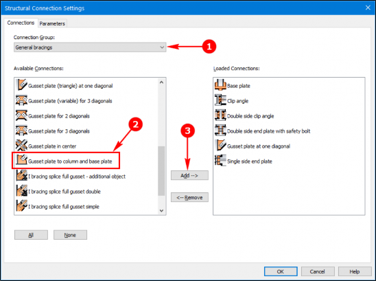
All the connections that were created inside advanced steel
02:45
are automatically displayed under the loaded connection
02:48
Any other connection that I want to use,
02:50
I can simply add that from the available connections category.
02:55
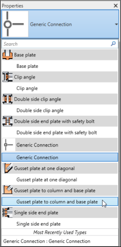
I can also filter the connection types.
02:57
In this case, I'm going to go and select the general bracings
03:02
And the one that I want to use is this one here, gusset plate
03:06
to column and baseplate.
03:09
I'm going to add this to the loaded connections category.
03:13
And now, I can use this.
03:16
To add the connection, I'm going to click on the connection
03:21
And now from the generic connection dropdown list,
03:25
I can pick the connection I want to apply which in this case
03:28
is gusset plate to column and baseplate.
03:33
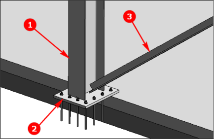
Now, I need to hold down the Control key
03:35
and select the elements.
03:37
So I'll first pick the column and then the baseplate
03:41
by holding down the Control key and then the bracing.
03:46
And now, I'm going to press Enter.
03:48
As soon as I do that, it not places a connection
03:51
but it comes up with an error message
03:53
because it is selected bracing as the second element
03:58
So all I need to do is drag this number three
04:01
tag onto the bracing.
04:05
And now it shows me the preview of the connection.
04:08
And now if I need to modify this instance,
04:10
I can go and click on this override by instance checkbox
04:15
and then edit the detailed parameters.
04:18
As I mentioned earlier, the options in these dialog boxes
04:21
are exactly the same as what we saw in advanced steel.
04:24
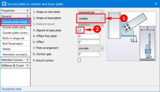
So in my case, under the gusset plate ship tab
04:28
I'm going to change the shape at dim or plate
04:33
and I'm going to pick variable.
04:36
And now I'm going to select the align to baseplate checkbox.
04:41
I'm happy with the rest of the parameters
04:43
so I'm going to close the dialog box.
04:46
A really cool thing is that if need be,
04:49
you can select this connection and you can
04:51
propagate it and Revit as well.
04:53
Similar to what we saw in advanced steel.
04:56
So a really simple, easy way of creating connections in Revit
04:59
and also propagating and copying them.
05:03
The last thing I want to talk about
05:04
is to control the visibility of all these structural connection
05:09
So then, I'm going to go into the visibility graphics.
05:12
There are a number of different shortcut keys
05:14
you could use to activate the dialog box.
05:16
I simply press VB key on the keyboard.
05:20
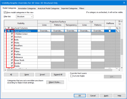
And now I'm going to expand the structural connections
05:28
And I can see all these connection elements.
05:32
If I clear this check box and hit the apply button, now
05:37
as you could see, none of these connection elements
05:39
are displayed in the model.
05:44
So if you want to simplify the model,
05:45
you can actually use this process.
05:47
But please not because the holes were
05:49
created on the structural sections, they are displayed.
05:53
Similarly, going back into the visibility graphics dialog box.
05:57
I [INAUDIBLE] structural connection category, apply.
06:04
Now this is also important, in cases
06:07
where structural template was not used to start the project.
06:12
In that case, by default the structural connection elements
06:17
So you have to first turn them on only then
06:19
you'll be able to see them in the model.
06:23
And that's all we have in this course.
06:25
I hope you enjoyed it.