Add and propagate connections - Exercise
Task 1: Add the base plate connection
- Open the Medical-Center-Connections.dwg file.
- Navigate close to the N5 grid intersection point.
- From the Home ribbon tab > Extended Modeling ribbon panel, click the Connection Vault tool to invoke the Connection Vault palette.
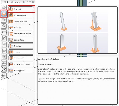
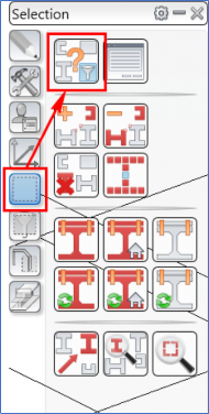
- From the left bar, invoke the Plate at beam category and then click the Base plate connection tool, as shown below. You are prompted to select the column.
- Select the column at the N5 grid intersection point. You are prompted to specify if you want to select an additional concrete object.
- Press ENTER to accept No as the value. The Advance Steel Base Plate dialog box is displayed.
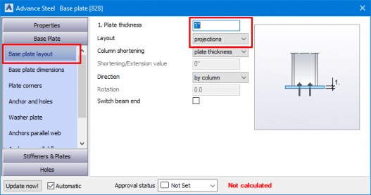
- In the dialog box, activate the Base Plate > Base plate layout tab and configure the settings, as shown below.
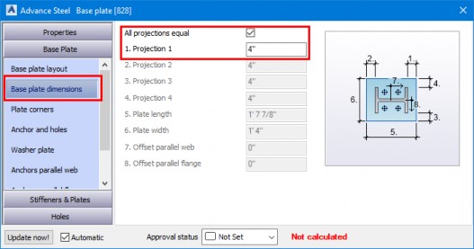
- Activate the Base plate dimensions tab and configure the settings, as shown below.
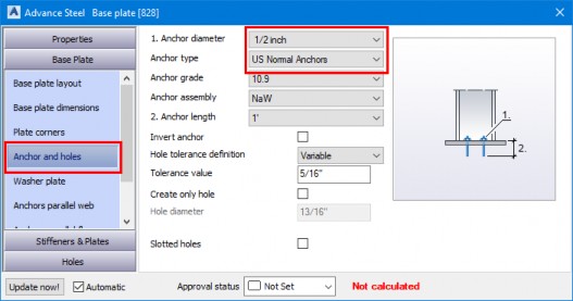
- Activate the Anchor and holes tab and configure the settings, as shown below.
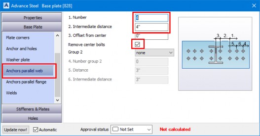
- Activate the Anchors parallel web tab and configure the settings, as shown below.
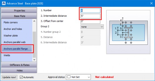
- Activate the Anchors parallel flange tab and configure the settings, as shown below.
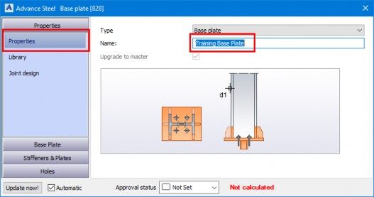
- Activate the Properties > Properties tab and configure the settings, as shown below.
- Add this connection to the library to be used in other projects.
Task 2: Propagate the base plate connection and review the copied connections
Propagating joints allow you to copy the joints at all the matching locations and maintain the parent- child relationship between the original joint and the copied joints.
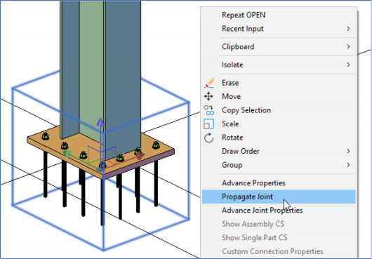
- Click on the connection box around the base plate connection you added in the previous task.
- Right-click in the blank area and select Propagate Joint, as shown below. The base plate joint is propagated to all the remaining columns.
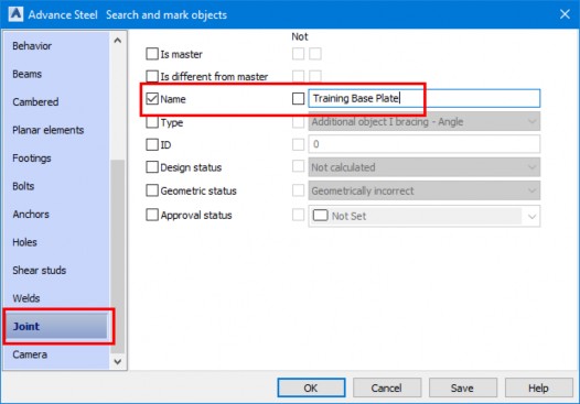
- From the Advance Steel Tool Palette > Selection category, click the Selection filters button, as shown below. The Advance Steel Search and mark objects dialog box is displayed.
- Scroll down to the Joint tab and configure the settings, as shown below.
- Click OK in the dialog box. The connection boxes of all the copied joints are highlighted in Red, as shown below.
- Type RE and press ENTER to regenerate the model.
Task 3: Add and propagate the end plate connection
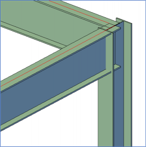
- Navigate to the top of the column to which you added the original base plate connection, as shown in the following figure.
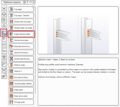
- From the Connection Vault, activate the Platform beams category and click the Single side base plate connection tool, as shown below. You are prompted to select the main beam.
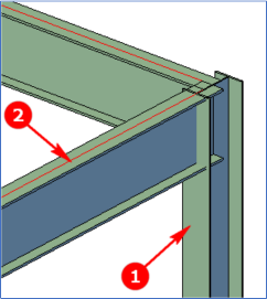
- Select the column labeled as 1 in the following figure and then press ENTER. You are prompted to select the secondary beam.
- Select the beam labeled as 2 in the following figure and press ENTER. The default connection is added and the Advance Steel Single Side End Plate connection is displayed.
- Activate the Plate & bolts > Plate – Alignment tab and configure the settings shown in the following figure.

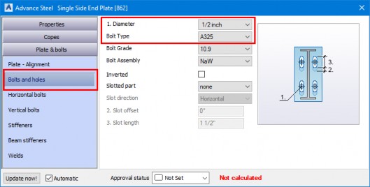
- Activate the Bolts and holes tab and configure the settings as shown in the following figure.
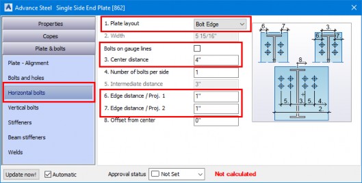
- Activate the Horizontal bolts tab and configure the settings as shown in the following figure.
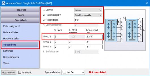
- Activate the Vertical bolts tab and configure the settings as shown in the following figure.
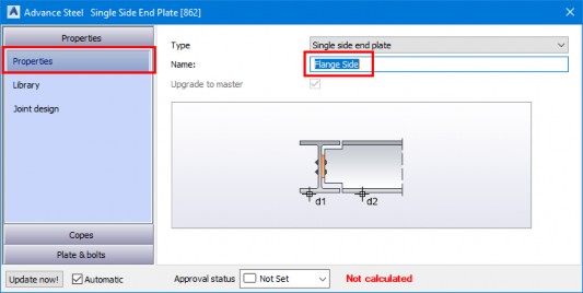
- Activate the Properties > Properties tab and enter the name of this joint, as shown in the following figure.
- Add this joint to the library and close the dialog box.
- Select the joint box of the end plate joint.
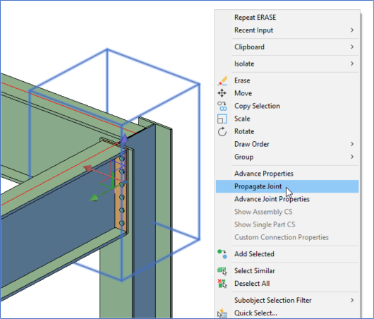
- Right-click and propagate this joint, as shown below.
- Using the method discussed in Task 2 above, highlight the places where this joint was copied.
- Delete any unwanted joint by selecting an element of that joint, such as the plate or the bolts. Refer to the video for details.
- Regenerate the model.
Task 4: Add a bracing connection
- Navigate to the bottom of the column at the F5 grid intersection point.
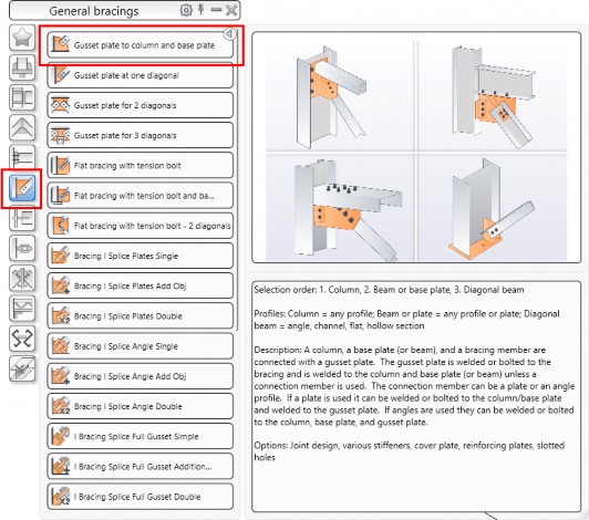
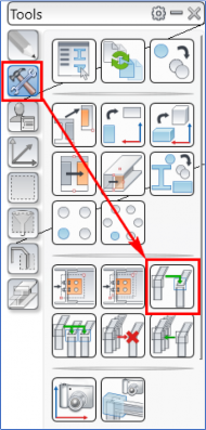
- From the Connection Vault, activate the General bracings > Gusset plate to column and base plate joint, as shown below. You are prompted to select the column.
- Select the column labeled as 1 in the following figure and press ENTER. You are prompted to select the beam/base plate.
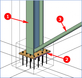
- Select the base plate labeled as 2 in the figure above and press ENTER. You are prompted to select the diagonal beam.
- Select the bracing section labeled as 3 in the figure above and press ENTER. The default connection is added and the Advance Steel Gusset plate to column and base plate dialog box is displayed.
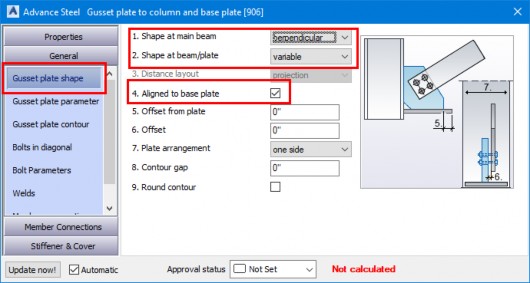
- Activate the General > Gusset plate shape tab and configure the settings shown in the following figure.
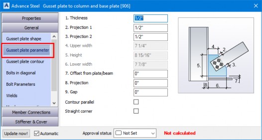
- Activate the Gusset plate parameters tab and configure all the settings shown in the figure below.
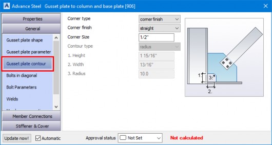
- Activate the Gusset plate contour tab and configure all the settings shown in the following figure.
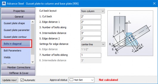
- Activate the Bolts in diagonal tab and configure all the parameters shown in the following figure.
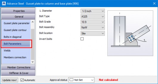
- Activate the Bolt Parameters tab and configure the settings shown in the following figure.
- Add this joint to the library and close the dialog box.
- Save the model.
Task 5: Copy the bracing connection
- From the Advance Steel Tool Palette > Tools category, click the Create joint in a joint group button, as shown in the following figure. You are prompted to select the connection part.
- Select any component of the bracing connection, such as the gusset plate, and press ENTER. You are prompted to select the column beam.
- Select the column at the J5 grid intersection point and press ENTER. You are prompted to select the secondary beam/base plate.
- Select the base plate of the column joint and press ENTER. You are prompted to select the diagonal beam.
- Select the bracing section and press ENTER. The joint is copied.
- Press ENTER again and click No in the Warning window.
- Save the model.
Task 6: Add other connections (optional)
- Using the Connection Vault, add other connections, such as Platform beams > Clip angle connection.
- Propagate or copy the connections.


